
So it requires some experimentation to find which equivalent IC is working well. The equivalent ICs we are mentioning here will not be the accurate alternative of TL072 in some cases but in some applications they will work good and in some applications they will not. Replacement, Equivalent, Or Alternative ICs / Part Numbers: The low noise and low harmonic capabilities with other features makes this IC ideal to use in high accuracy applications. The IC is also THD (Total Harmonic Distortion) free which is also useful if you are making any type of audio preamplifier circuit with this IC. Both the operational amplifiers of the IC have very low current consumption and each opamp only consume 1.4mA normally. The input stage of the TL072 contains JFET transistors which insures lower noise as compare to the BJT transistors. The single version (TL071) contains one opamp while the quad version contains four separate operational amplifiers inside due to which the package is different and it contains 14 pins. There are also single and quad version of this IC which are TL071 and TL074. The internal circuitry of IC contains two separate operational amplifiers that can be operated with single or dual supply. TL072 is a very popular operational amplifier IC available in 8 pin dip and other packages. Quiescent current is only 1.4mA to 2.5mA.Dual operational amplifiers in a single package.But the start and stop voltages will be set according to the battery’s voltage.TL072 IC Features / Technical Specifications: The same procedure is done for other batteries. The circuit is tuned now you can connect the power supply back and remove the adjustable power supply. Now to set the start voltage of charging change the voltage of the adjustable power supply to 5.9V. Now replace the power supply in this circuit with the adjustable power supply and do not connect any battery with the circuit. Since the voltage of a fully charged 6V battery s 7.3V on a DMM so set 7.3V on the adjustable power supply. For that, you will need an adjustable power supply and follow these steps.

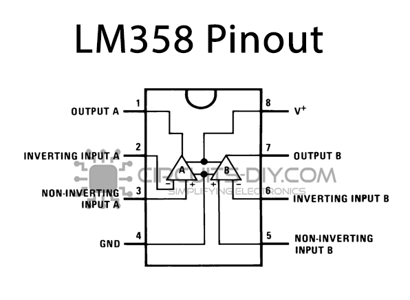
Circuit TuningĪ simple tuning needs to be done to charge the battery automatically. In this way, it will switch ON the whole charger circuit from the mains when the battery needs to be charged and switches off when the battery is charged fully. You can connect the relay to the main plug of the power supply. The LED4 will indicate that the battery is getting charged. When the battery’s charging is full LED1 will glow. They are used to set start and stop voltages for the charging process of the battery. Both are connected with variable resistors VR1 and VR2. These two op-amps are working as a comparator to detect the voltage of the battery. We are using an operational amplifier IC LM358 that has two built-in op-amps.


 0 kommentar(er)
